

A flat roof specified without a design framework is an unwanted financial risk. The membrane will be identified as the culprit when water finds a way through, yet the source of the problem will be the build-up not matching the local conditions, insufficient slope to drain, omitted wind uplift details, or poorly executed connections. This article discusses key issues that should be addressed before work starts on-site, including things that can go wrong with who’s responsible for what detailing.
Table of Contents
The Fall Myth and Why Ponding is a Design Failure
Begin here because the language is deceiving. A “flat” roof isn’t flat. Water must flow toward outlets at a minimum of 1:60 over the membrane before it stands there. Ponding water isn’t an aesthetic nuisance – it adds weight, speeds up UV degradation, harbors dirt, and provides the ideal environment for the biochemistry that breaks down all but the most impervious materials regardless of the specification.
Falls must be integral to the structure, not an afterthought sprayed on with tapered insulation. Tapered insulation has unexpectedly become a necessary evil for too many roofs because the fall wasn’t specified from the start and the geometry wasn’t worked out by someone who can visualize where water will truly collect on a real-world roof plan. Drains must always be located at the low points and sized for the low frequencies. This is a design requirement, not an after-the-fact detail, and it must be shown on the architect’s plan, not in the roofing contractor’s site book.
Comparing the Three Main Build-up Options
Warm, cold, and inverted roofs should not be used interchangeably. They have different condensation risks, insulation efficiencies, and maintenance implications.
The warm roof is the most commonly used flat roof construction. With insulation located above the structural deck, the deck is kept at internal temperature. As long as any vapour control layer (VCL) is correctly located under the insulation, the structural deck does not experience the extremes of the external thermal environment and so risk of condensation is largely eliminated. Most modern, commercial, and domestic flat roof systems incorporate this detail which is considered industry good practice. The ease with which the roof can be insulated is also often a key deciding factor in energy-efficient construction making the warm roof the default choice. The deck is protected, the thermal mass is an advantage rather than a problem, and specifying a warm roof can potentially be made fully accessible or planted without losing advantages of the basic form.
The cold roof is much less common as a flat roof build-up for commercial construction, primarily because of the complexity and risk associated with designing exactly the right amount of cross ventilation into the void left between the deck and the top surface of the insulation boards. If this ventilation proves to be inadequate, condensation quickly builds up to unacceptable levels. We would not choose a cold roof for new construction unless we had deep pockets, an easily insulated and drained deck, and unlimited opportunity to check (after each seasonal variation) if the ventilation space inside the deck’s soffit extends to every corner and if it’s all properly open.
The inverted roof does exactly what it says on the tin – a warm roof has all its components turned on their head. Insulation is installed over and outside of the membrane, which protects it from UV and thermal stresses. The system works well but only if the insulation is extruded polystyrene (XPS) board type which resists the uptake of moisture, and the drainage calculations must account for water flowing below the boards. Great for ballasted and accessible deck applications, but if you only count the drainage boards on your spreadsheet then you’re missing the point.
Warm roof design is generally recommended. More discussion is to be had regarding the detailing of the insulation, what material exactly should the insulation consist of.
Selecting the Membrane: Single-ply Versus Built-up Systems
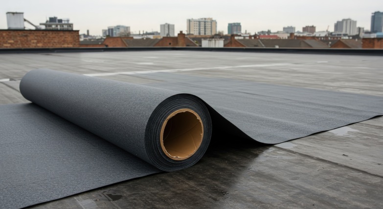
A built-up bituminous system may be appropriate in specific situations – for example, in a heavy-traffic application like a roadway, or where specified by a municipal heritage or conservation authority. But, as far as new flat or low-sloped commercial rooftop installations are concerned, truly sustainable design and construction considers the expectation of a building over its economically viable service life – 60-plus years. In this context, the preference for single-ply PVC, TPO, or EPDM membranes is based on long-term performance, reduced risk of failure, and the fact that they remain weldable, joinable, and repairable throughout their projected service life.
Between PVC, TPO, and EPDM it generally depends on the application. PVC has the longest commercial track record and the broadest suite of colours and solar reflectance options. TPO has great chemical resistance and is well-suited for roofs that may be exposed to oils or other potential contaminants. EPDM, the synthetic rubber membrane, is best for roofs with complex geometry because it is extremely flexible at low temperatures and cold-applied jointing is very simple.
As important as the choice of membrane type is the system the membrane is a part of. An architect should specify a single-ply system from a manufacturer who designs the whole build-up – membrane, substrate board, VCL, and drainage components – and wraps it all up into a single warranty. A supplier like alwitra offers EPDM and PVC membrane systems in addition to certified roof drainage components, so the spec doesn’t split across multiple manufacturers where the devil is in the detail of interfaces.
The Vapour Control Layer: Where Warm Roofs Fail Without One
To be effective, a VCL has to be located exactly where it is meant to be, and then it has to be maintained continuously across the entire deck area, including around all penetrations and at all upstands. Its purpose is to stop warm, humid internal air from allowing the roof build-up to reach the dew point – which is what occurs when the temperature differential between inside and outside is large and the inside moisture load is high.
For standard office or residential use, a standard polyethylene VCL with the appropriate lap sealing is usually sufficient. For high-humidity interiors – commercial kitchens, swimming pools, laundries, atrium spaces – the vapour pressure difference is high enough to expect a higher-performance VCL, often a reinforced foil type, and the specification should require a condensation risk analysis using BS EN ISO 13788 methodology before the build-up is finalised.
The common failure mode isn’t specifying the wrong VCL – it’s specifying one and then either watching it get punctured during installation by the following trades or leaving it unspecified at the perimeter so it terminates 200 mm short of the upstand. The VCL must be treated as a continuous layer, not a roll of plastic that gets laid and forgotten.
Wind Uplift: Calculation, Not Assumption
Wind uplift is the determining factor in whether a single-ply system should be mechanically fastened, fully adhered, or ballasted. You don’t get a slow leak from getting this wrong, you get a membrane that delaminates or lifts in a storm. This is calculated risk, not guesstimated risk.
The correct reference is BS EN 1991-1-4, which details the method by which you calculate wind loads taking into account building height, terrain category, exposure, and roof geometry including parapets. Parapets reduce uplift loads at the perimeter – nice to know as this directly influences fastener density and pattern in the critical edge zones.
Mechanically fastened systems are fixed by screws and plates driven through the membrane into the deck, which is quick and easy to inspect. Fully adhered systems bond the membrane directly to the insulation substrate – which looks better, takes longer, and performs better in areas where penetrations make fastener placement difficult. Ballasted systems – gravel or paving slabs on an inverted roof – are only an option where the structure can accommodate the extra load and the calculated wind uplift is so low that dead weight alone is sufficient.
Don’t take the contractor’s word for it here. Get the sums done, written down, and referenced in the spec.
Drainage as Part of the Waterproofing System
Outlets and drainage are not outside of your waterproofing specification; they are part of it. In fact, a high-performance membrane that drains slowly or inadequately will fail in front of a more modest membrane that drains well. Standing water is a constant mechanical and chemical stress, and it’s often psychological; clients worry whether ‘that little bit of water’ will track dirt into the building.
Primary outlet positions are determined by the fall design. Secondary outlets or overflow weirs must also be specified and positioned to suit the fall or design flood-scenario blockage. This is frequently overlooked until a blocked outlet produces a flood in a building where the structural deck wasn’t designed for the resulting water load. This is an all-party error because the waterproofing contractor, building owner and architect should share liability.
For large commercial roofs, siphonic drainage systems can be worth serious consideration. These use vacuum-induced flow to pull water at high velocity through smaller bore pipework. This has structural and program advantages. They are also more tolerant of concentrated, short-duration rainfall events since they can remove water faster than conventional gravity systems for the same outlet size.
The architect must include in the specification the types of outlet, their positions, minimum rim diameters, and the required flow rate. It is an architect’s decision, not a site decision.
Detailing: Where Warranties Are Earned or Voided
Most of the failures of flat roofs start in the small details rather than in the central field of the membrane. A membrane seam across the mid-point of a roof will last longer than almost any other part of the surface. The same membrane wrapping up an uneven parapet, turned down and bonded with varying care to sufficient but not specified adhesive and without any mechanical restraint at the top edge, will be the first thing to fail – often within two or three years.
The rules are not difficult, but they have to be written down in all their banality. Upstands at all perimeter walls and penetrations shall be a minimum of 150mm above finished roof level – not 150mm from the structural deck, 150mm from the top of the gravel, 150mm from the bottom edge of some cladding – 150mm above the surface. Internal and external angles at upstands require pre-formed or in-situ moulded details. The membrane must not just be folded round the corner. No good waving vaguely at the return – the return must be detailed with a precision you never knew you had in you.
Third-party Certification and Why it Belongs in the Tender Document
Not describing what “equal” means when specifying a membrane will likely lead to substitution during the tender phase. When you are presented with the lowest bid and an unrecognised system, the pressure to accept it can be overwhelming. The solution is to issue a performance specification that is so stringent that equivalence of any substitution needs to be demonstrated on paper.
In the UK, BBA certification is the go-to benchmark for specifiers. It adds confidence that an independent body has evaluated the product system’s fitness for its intended use. CE marked membranes are assessed against BS EN 13707 for reinforced bitumen systems and the relevant harmonised standard for single ply will give you the requisite paperwork for proving your performance spec. For root resistance, you can use the FLL shortcut for compliance with green roofs. Otherwise, you’ll end up with a manufacturer you like and finding out that their membrane is incompatible with your proposed planting medium.
Warranty can be a performance issue but isn’t the same as certification. A 20-year-plus manufacturer and insurance backed warranty that covers both materials and workmanship when installed by an approved contractor is a legitimate requirement. A warranty of 10 years with a “get out” clause that detail design is the specifier’s risk is commonly offered and largely meaningless – read the small print.
Performance, Sustainability, and Future-Proofing the Asset
Having a flat roof that keeps performing for 40 years is a far-reaching sustainability measure on its own. An uninsulated roof can account for 25% of a building’s total heat loss (Energy Saving Trust), which means insulation specification and thermal continuity are key to operational carbon performance, not just regulatory compliance.
Cool roof membranes with high solar reflectance directly reduce cooling loads in summer and contribute to urban heat island mitigation – a real performance benefit in dense urban areas, not just a box-ticking exercise. PVC and TPO can be manufactured in white or light grey with reflectance properties at or above standard cool roof thresholds, without the need for additional coating application. Green roofs add stormwater attenuation and biodiversity net gain to the same protected membrane build-up, provided the membrane carries FLL-certified root resistance. PV arrays can be mounted on ballasted rail systems on an inverted membrane without penetrations. Both work best when the membrane and drainage system are designed from the start to accommodate them.
These RIBA Stage 3 decisions determine whether any of it can be achieved at all. If the roof design is minimum cost with no thought for longevity, you’ve creatively ruled out every one of these options. End of. However, a roof based on long-life performance leaves those decisions open – and that’s what a client commissioning a 40-year asset should be able to expect.
